

Miles' Equation
Ryan Simmons
NASA Goddard Space Flight Center
May 2001
Basics of Miles' Equation
The following equation is attributed to John W. Miles.

| Where: | |
| GRMS = Root Mean Square Acceleration in G's (sometimes given as ÿRMS). | |
 = Transmissibility (or amplification factor) at = Transmissibility (or amplification factor) atwhere |
|
| [ASDinput ] = Input Acceleration Spectral Density at |
 In 1954, Miles developed his version of this equation for GRMS as he was researching fatigue failure of aircraft structural components caused by jet engine vibration and gust loading. Miles simplified his research by modeling a system using one degree of freedom only. He also applied statistical advances that had been made at the time. While his goal was to analyze the stress of a component, the equation can be rearranged and used to determine, among others, displacement, force, and, in our case, acceleration.
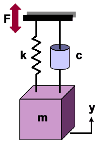
- Single Degree Of Freedom System - Miles' Equation is derived using a single degree of freedom (SDOF) system (lightly damped), consisting of a mass, spring and damper, that is excited by a constant-level "white noise" random vibration input from 0 Hz to infinity. Miles' Equation is thus technically applicable only to a SDOF system.
This figure shows a typical representation of a SDOF oscillator. The mass (m) is attached to the spring (stiffness k) and the damper (damping c). The system is forced by the random vibration function (F) in the y-direction only.
Derivation of Miles' Equation is left up to you. The references at the bottom of the page provide different methods of deriving the equation, so reviewing each method could provide insight into Miles' Equation.
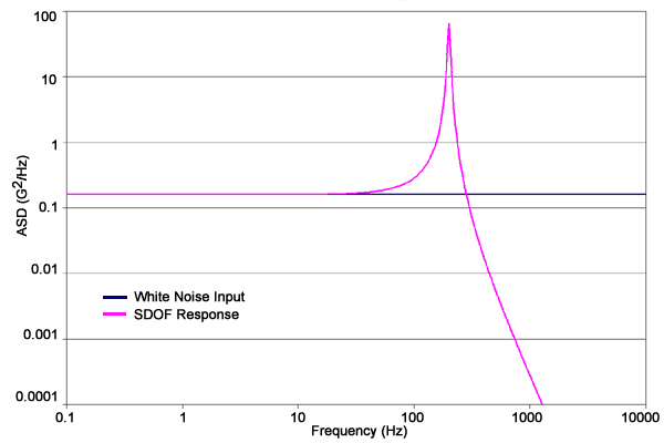
- SDOF System Response Plot - The plot below shows the input and response of a SDOF system. Miles' Equation calculates the square root of the area under the response curve, providing us with the GRMS value.

SDOF System Response Plot
 - Response Parameters - Miles' Equation can also be used to predict other response parameters such as stress or displacement. For example, the displacement equation for YRMS is given here. Displacement can in turn be used to calculate the stress.
NOTE: in this form of the equation, since we want units of length, the ASDinput must be in units of [length/sec2]2/[Hz]. You will most likely have to convert your ASD data from g2/Hz to something else.
USES OF MILES' EQUATION
- Design - During the design of a part, if enough analysis has been performed to determine the part has a predominant resonant frequency, then Miles' Equation can be used to estimate the loads due to random vibration. Just calculate the GRMS value and multiply it by 3. That's the "three-sigma" load. Keep in mind, this is conservative.
- Testing - Accelerations due to random vibration at resonant frequencies in a multiple degree of freedom system can be approximated using Miles' Equation. This will indicate how much of the overall RMS acceleration is occurring at a resonant peak of interest compared to the complete frequency spectrum.
MISUSES OF MILES' EQUATION
- Miles' Equation Does NOT Work in Reverse - Accelerations cannot be determined during random vibration testing using Miles' Equation. An upper bound on loads can be calculated using the 3-sigma value, but that's about it. In other words, a part designed to 3-sigma equivalent static loads will survive a random vibration test. However, Miles' Equation cannot be used to predict the failure of a part designed to less than 3-sigma levels.
- Miles' Equation Does NOT Give an Equivalent Static Load - Calculating the GRMS value at a resonant peak after a random vibration test and multiplying it by the test article mass does not mean that the test article was subjected to that same, equivalent static load. It simply provides a statistical calculation of the peak load for a SDOF system. The actual loading on a multiple DOF system due to random input depends on the response of multiple modes, the mode shapes and the amount of effective mass participating in each mode. Static testing must still be done.
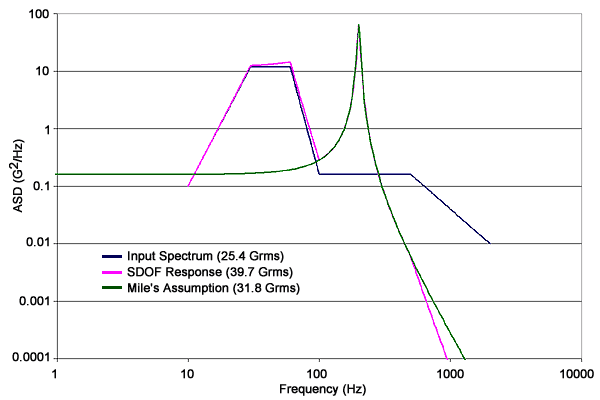
- Miles' Equation may not be Conservative for a Shaped Input Spectrum - Miles' Equation is based on the response of a SDOF system subjected to a flat random input. If Miles' Equation is used to calculate the GRMS response to a shaped input spectrum, the result will not accurately reflect the rigid body response below the resonant frequency. If the shaped input spectrum has high ASD levels below the resonant frequency, then Mile's Equation may significantly underpredict the GRMS response. The following plot shows this condition. Note that the Miles' assumption has a response of 31.8 GRMS while the actual SDOF response is much greater at 39.7 GRMS. This demonstrates that Miles' Equation is best used when the input ASD is flat or nearly so.

Shaped Input Spectrum and Response
REFERENCES
- John W. Miles, On Structural Fatigue Under Random Loading, Journal of the Aeronautical Sciences, pg. 753, November, 1954.
- Dave S. Steinberg, Vibration Analysis for Electronic Equipment, Wiley-Interscience, New York
- Thomas P. Sarafin (editor), Spacecraft Structures and Mechanisms: From Concept to Launch, Microcosm, Inc., Torrance, CA, 1995
Thanks to Scott Gordon and Bob Coladonato for their invaluable assistance in the creation of this page.
Ryan Simmons
May 2001