


Development of Fixed-Base Shake Transfer Functions
Timothy Carnahan
Goddard Space Flight Center
January 23, 1996
The block diagram below is for a typical feeback servo control system in an instrument.
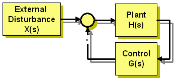
The plant, H(s), will generate some error signal of a sensor. In motor systems this is typically an error between the rotor and the stator. The controller senses these errors and applies a correction load. For rigid systems the external load would be applied to the mass of the system to generate a disturbance acceleration. The more complex systems are flexible. This could mean that the flexibility is in a rotational shaft or between the point of application of an external load and the instrument. For the CIRS scan mechanism a flexible plant model was desired to couple spacecraft disturbances at the base of the instrument with sensor errors between the reference interferometer and the scan mirror. Since the S/C is supplying a disturbance without concern for the response of the instrument, the plant model assumes the instrument is fixed to ground. Further, the S/C generates disturbance forces and moments at the base of the instrument.
The following is the methodology and derivations developed to provide the controls analyst with H(s). This is expressed as a transfer function of coefficients to a numerator/denominator pair.
The general equation of motion that governs an undamped systems without external forces is:
![]() (1)
(1)
For a system with fixed base motions acceleration, ![]() , equation 1 becomes
, equation 1 becomes
![]() (2)
(2)
if we define ur = u - uB and ![]() then equation (2) becomes
then equation (2) becomes
![]() (3)
(3)
Expressing ur in model coordinates we get:
 (4)
(4)
Where ![]() is a fixed base mode shape for mode i and qi are the model coordinates.
is a fixed base mode shape for mode i and qi are the model coordinates.
Converting equation (3) to model coordinates and pre-multiplying by ![]()
![]()
![]()
![]() (5)
(5)
For m =![]() , the modal mass, and k =
, the modal mass, and k = , the modal stiffness, in equation (5) and including generalized modal damping of
 ![]() we get:
we get:
![]()
![]()

 (6)
(6)
Solving equation (6) for q(s) and using 
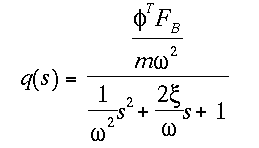 (7)
(7)
Using equation (7) in equation (4) to solve for ur
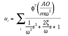 (8)
(8)
Solving for u
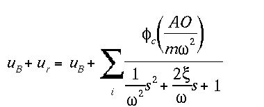 (9)
(9)
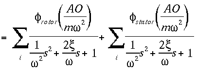
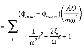
For relative rotor/stator T.F. we want the difference between the two or,
ustator - urotor = durotor-stator which expands to
 (10)
(10)
![]()
![]()
 (11)
(11)
For absolute stator T.F. we want a complete solution to u. Remember that that equations of motion, (2), was in terms of acceleration and therefore,
uB(s) = ![]()
ustator = ![]()
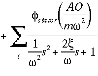 (12)
(12)
Equations (11) and (12) need four inputs, m (the modal mass for mode i), ![]() (the mode i canterlevered shapes),
(the mode i canterlevered shapes), ![]() (the eigenvalue for mode i),
(the eigenvalue for mode i), ![]() (generalized modal damping), and AO. For mass normalized eigenvectors m is unity and can be eliminated from the problem. AO is defined as
(generalized modal damping), and AO. For mass normalized eigenvectors m is unity and can be eliminated from the problem. AO is defined as
–![]() M
M![]()
The 'motion' program processes the output of a normal modes run, rigid format 3, and generate the H(s) T.F. for Matlab. The DMAP for UAI NASTRAN version 11.8 to solve for AO and output to an OUTPUT4 file is shown below.
ASSIGN AOout=aOout.ot4,NEW,USE=OUTPUT4,TYPE=FORMATTED
ALTER 188 $
MATGEN BGPDT,EQEXIN,CSTM/UB/102/0/ $ GENERATE Ub
MPYAD MGG,UB /FB/0/ -1/0/ $
MPYAD PHIG,FB, /AO/-l/l/O/ $
OUTPUT4 A0,,,,//*AOout*/0 /*FULL*/ $
ENDALTER $
The eigenvalues and eigenvectors are read from a punch file. In order for the post-processing program to work the following guidelines must be observed:
- Because m is not exported to a file the eigenvectors must be mass normalized. (Therefore, m is the density matrix.)
- Do not use DYNRED, as it changes the set definitions and the DMAPS MPYAD does not use the correct size arrays.
- Use DISP(PUNCH)=set id to output the grid points of interest. The punch files are much smaller when only a set, the rotor/stator gid and the input gid, are in the punch file. The punch file includes the eigenvalues.
The 'motion' program is written in "C" to read the NASTRAN data and convert it into MATLAB m-files in the form of MATLAB numerator and denominator transfer functions. This program is located in /home/tim/bin and was written for SGI machines. Motion has been ported to an IBM RS6000. The source code is in the directory /home/tim/bin/SRC/NASTRAN. The data used by the "motion" program will come from a punch file which contains the eigenvectors and eigenvalues and the OUTPUT4 file of the A0 matrix. With these the program asks for the grid points and dof for the rotor and the stator and the direction of input disturbance. When the desired output is to know absolute position, stator only, the same grid id is entered for rotorr and the slator. Motion will add the needed MATl,AB commands to generate both the position and acceleration transfer functions for absolute displacement. The MATLAB variable names of these absolute transfer functions is pos_num and pos_den for position transfer functions and acc_num and acc_den for acceleration transfer functions. In the case of relative transfer functions only the position transfer functions are generated and the MATLAB variable names are plant_num and plant_den. The translational units of the transfer function are in whatever units the NASTRAN model was in. The rotational units are in degrees.
The 'motion' program is coded with the following maximums: Number of eigenvalues = 230. Note: matlab can not accurately handle such a large number of eigenvectors/T.F.'s. A method of mode selection is needed to provide only significant modes for controls work. The generalized modal damping, ~, is set to 0.1% of critical. This damping values depend on a number of mechanical characteristics from the magnitude of the applied structure to the type of assembly. For typical micro-gravity disturbances on small, < 100 lbs, a value of 0.1% is considered conservative.