


Notes Concerning Yield Criteria
Dr. John McGuire - July 6, 1995
Formerly of the Goddard Space Flight Center
Contact: Jim Loughlin - NASA GSFC
Tresca Yield Criteria (Max Shear Stress)
Von Mises Yield Criteria
Bi-axial Stress
A Few Definitions
- Yield Stress = sigma y
Ultimate Stress = sigma u
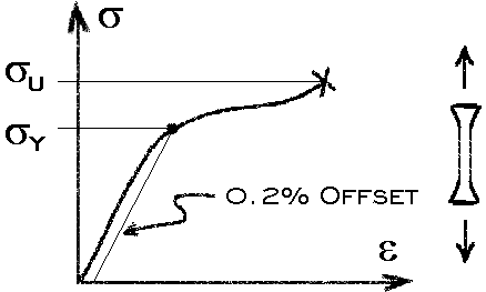
Figure 1. Typical Stress-Strain Curve for Ductile Metals
Sigma y and sigma u are determined from uniaxial tensile tests. Since the exact point at which yield occurs may not be visually obvious it must be defined in some other consistent manner. For most ductile metals the following convention has been widely accepted. The yield point is determined using a line parallel to the linear portion of the curve and originating at epsilon = 0.002 (The 0.2% offset method).
Since several tests of the same material will result in slightly different values for sigma y and sigma u, a statistical approach must be used to determine the exact value that will be used. For example: stress values listed in the military handbook (MIL-HDBK-5F) are catagorized as A-Basis and B-Basis. Quoting from the hand book:
- A-Basis. -- At least 99 percent of the population of values is expected to equal or exceed the A basis mechanical property allowable, with a confidence of 95 percent.
- B-Basis. -- At least 90 percent of the population of values is expected to equal or exceed the B basis mechanical property allowable, with a confidence of 95 percent.
From this it can be seen that just determining what value to use for the yield stress requires some thought.
A Few More Definitions (for bi-axial stress)
- Normal Stress in x direction - sigma x
Normal Stress in y direction - sigma y (not the same as yield stress)
Shear Stress in xy plane - tau xy
Principal Stresses - sigma 1 and sigma 2
For a 2D plate the state of stress at a point can be described using any arbitrary axis. The state of stress using this axis will be described by the values sigma x, sigma y, and tau xy.
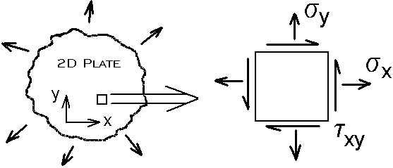
Figure 2. State of Stress Described Using Arbitrary Axis
There will exist some orientation of the axis at which when the state of stress is described, the shear stress will be zero. The axis when oriented at this angle is called the principal axis. The normal stresses for this special orientation are defined as the principal stresses, sigma 1 and sigma 2.
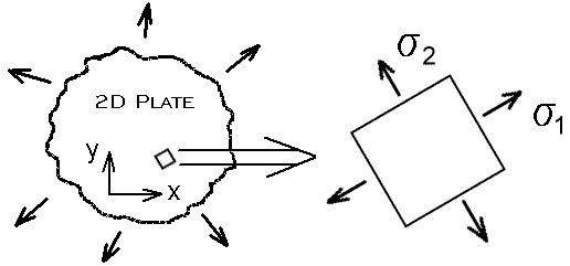
Figure 3. State of Stress Described Using the Principal Axis (tau xy = 0)
Tresca Yield Criteria
(Max Shear Stress Yield Criteria)
Tresca postulated that a material under a multi-axis state of stress will yield when the Max Shear Stress reaches some critical value. Using this assumption the yield envelope for a bi-axial state of stress is as shown in Figure 4. (Note: sigma y in Figure 4 is the yield stress)
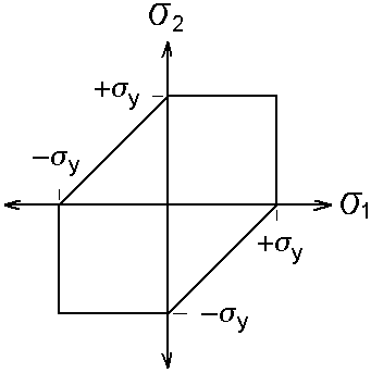
Figure 4. Tresca Yield Envelope
Why the yield envelope takes this shape can be illustrated by inspecting Morh's circle for various states of stress. First, consider the uniaxial tensile test at the moment yield occurs (Figure 5.). For this case one of the principal stresses will be equal to the yield stress and the other principal stress will be zero. This condition defines the critical value of the shear stress at which yield occurs. According to Tresca, yield will occur only if the shear stress exceeds this value. It should be noted that this value is half the value of the yield stress.
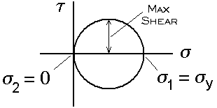
Figure 5. Mohr's Circle for Uniaxial Stress Test
If either of the principal stresses exceed the yield stress, the out of plane shear will exceed the Max Shear value (see Figure 6.). This is because for 2D problems the out of plane principal stress (sigma 3) is assumed to be zero. Therefore, neither sigma 1 nor sigma 2 may exceed sigma y.
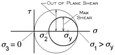
Figure 6. Mohr's Circle for sigma 1 or sigma 2 Greater than sigma y
In the case where one of the principal stresses has the opposite sign of the other (i.e. one in compression the other in tension. Quadrant 2 and 4 of the Tresca yield envelope) yield will occur before either of the principal stresses reaches the yield stress. As illustrated in Figure 7. if sigma 2 becomes more negative sigma 1 must also decrease (Other wise the shear stress will increase beyond the max value). Essentially you may slide a constant size circle along the axis between positive and negative sigma y.
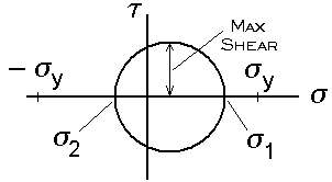
Figure 7. Mores Circle for Principal Stresses of Opposite Sign
Von Mises Yield Criteria
Von Mises postulated (1913) that a material will yield when the distortional energy at the point in question reaches a critical value. The distortional energy written in terms of the 2D principal stresses and the yield stress is as follows.

Figure 8. shows the VonMises Yield envelope superposed over the Tresca yield envelope. The scatter of test data is such that either criteria is as applicable as the other. For hand calculations Tresca is easy to implement; for a computer program VonMises is convenient because the entire envelope can be represented with a single equation.
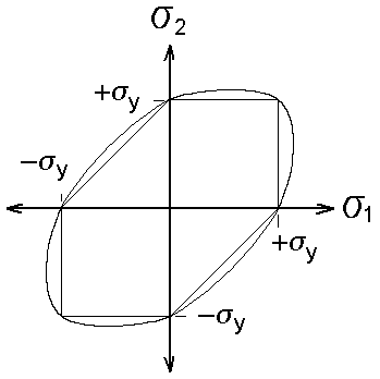
Figure 8. Von Mises Yield Envelope
Dr. John McGuire