

Finite Element Modeling of an Adhesive in a Bonded Joint
Farhad Tahmasebi, Ph.D.
NASA Goddard Space Flight Center
July, 1999
A practical finite element approach has been developed to model the adhesive in a bonded joint. Numerical examples have shown good agreement with classical solutions.
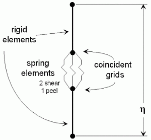
 The method uses a gap the thickness of the adhesive, two rigid elements, and three zero-length spring elements between coincident nodes. One rigid element stretches from one adherend to a node at the center of the gap, while the second rigid element stretches from the other adherend to a coincident node also at the center of the gap. The spring elements connect the two rigid elements between the coincident nodes. The figure show the layout. For clarity, the coincident nodes are shown separated. No rotational springs are used in this modeling technique.
Forces, stresses, strains, etc., can be recovered directly for the adherend elements. Recovery of spring forces and deformations can in turn be used to determine the stresses and strains in the adhesive.
The various spring stiffness values are determined using the following equations. Note that there are different values depending on whether the spring elements are internal to, along the edge of, or at a corner of the finite element mesh.
Ael = Element area
G = Shear modulus of the adhesive
![]() = Adhesive thickness
= Adhesive thickness
E = Young's modulus of the adhesive
![]() = Poisson's Ratio
= Poisson's Ratio
Shear spring constant, ks, in both lateral directions, 
Peel spring constant, kp, through the thickness, 
where ![]()

where 

where 
Output results for the adhesive can be calculated using the following equations:


where
i = Grid number
x, y = Shear directions
z = Peel direction
![]() = Spring deflection
= Spring deflection
![]() = Peel strain
= Peel strain
![]() = Spring force
= Spring force
![]() = Shear strain
= Shear strain
![]() = Peel stress
= Peel stress
![]() = Shear stress
= Shear stress
I have written two FORTRAN programs which obtain stresses and strains in bonded joints using the above formulations. For a given bonded joint model, these programs read the corresponding NASTRAN input and output files, use the spring forces or deformations to obtain the adhesive stresses or strains at the mid-plane grid points, sort the stresses and strains in descending order, and generate Mathematica plot files for 3D visualization of the stress and strain fields.
The following files are source codes and must be compiled in order to run them.
- adhsv_strs.f - FORTRAN source code for extracting adhesive stresses
- adhsv_strn.f - FORTRAN source code for extracting adhesive strains
You can view or download a memo, Software Tools for Analysis of Bonded Joints in .pdf format that describes the two programs in detail.
NOTE:
The grids and springs can be numbered in any order. The programs
determine the pairs of grids which are initially coincident, and the
spring triplets which correspond to such grid pairs. In the earlier
attempts at NASA/GSFC to model adhesives in bonded joints, the analyst
had to number the grids and/or springs in specific orders so that the
XYZ spring triplets acting between pairs of initially-coincident
adhesive grids could be identified. Such ordering of grids and/or
springs can be very time-consuming. For more information, refer to the
above memorandum.
- REFERENCES:
- K.R. Loss and K.T. Keyward, Modeling and Analysis of Peel and Shear
Stresses in Adhesively Bonded Joints, AIAA paper 84-0913.
- L.J. Hart-Smith, Adhesive-Bonded Double-Lap Joints, Technical Report NASA CR112235, Contract NAS1-11234, McDonnell Douglas/Douglas Aircraft Co., Jan. 1973.
- L.J. Hart-Smith, Design Methodology for Bonded-Bolted Composite Joints, Final Technical Report AFWAL-TR-81-3154, Vol. I, Contract F33615-79-C-3212, McDonnell Douglas/Douglas Aircraft Co., Feb. 1982.